How to enable secure and convenient key-based SSH authentication (the easy and automagic way)

Recently I was up to the task of improving the SSH security on multiple servers. I was going to replace the less secure password based authentication with the more secure method of using SSH keys, which also has the added benefit of being more convenient as I do not have to type my password each time I login to the servers.

And being a really big fan of automation, and especially to avoid reproducing boring and repetitive tasks, I thought I might find and smarter and easier way than remembering all those steps needed for each machine. So I decided to write an automagic AllowSSH bash script for this. This way I could perform the task easily and more reliably on multiple hosts (and it will be far easier to remember in the future). This is how the script is used:

$ ./AllowSSH root@192.168.100.100

Before running the script you need to make sure you have a SSH RSA key generated and that you are logged in as the user you want to grant access to the remote machine. Se details below with an description of what the script actually does.

The easiest way to install the AllowSSH-script to your local computer is running the following command:

$ curl -L http://bit.ly/install-allowssh | bash

Read More

Install Visual Studio for Mac preview (the easy way)

If you are interested in evaluating the new Visual Studio for Mac (Preview) from Microsoft, the easiest way to install Visual Studio on your Mac is to simply open up a terminal window and execute the following command:

$ curl -s https://git.io/mikaelleven-vsformacprev | sh

This will download the disk image, execute the installer and remove the disk image when the installation has finished.

If you want to preview the script before executing it (which I strongly encourage) navigate to the url https://git.io/mikaelleven-vsformacprev or choose to Read more below.

Read More

How to fix empty system log (“syslog”) on Linux

If your system log (“syslog”) file is empty something is probably wrong. Under normal conditions the system writes to this log all the time and you can easily verify this by executing the following command.

$ cat /var/log/syslog

If everything is working as expected a lot of log messages should be printed on screen. If the syslog however is empty this might be caused by faulty file permissions (wrong owner). You can also try to post a test message to the log yourself to ensure nothing actually gets written to the log.

$ logger This is a test message
$ cat /var/log/syslog
Nov 13 19:58:12 MyComputer root: This is a test message

The result should now look something like the above if the syslog is actually working. If the file however is still empty then you need to verify the file permissions using the ls command:

$ ls -l /var/log/syslog
 -rw-r--r-- 1 root adm 21874 Nov 13 19:35 /var/log/syslog

Here you want to make sure the owner is syslog and the group is adm. If the owner is something other than syslog (as in this example where the owner is root) you could easily solve this by simply change the owner of the file so the “syslog” user can write to the syslog-file:

$ chown syslog:adm /var/log/syslog

Now you can once again run the ls command to make sure file permissions (ownership) is as expected:

$ ls -l /var/log/syslog
-rw-r--r-- 1 syslog adm 21874 Nov 13 19:35 /var/log/syslog


Getting started with SPI & analog input in NodeJS using Raspberry Pi and MCP3008

RaspberryPi_B+_GPIO_SPI_MCP3008_breadboard_mikael-levenAlthough Raspberry Pi does not support reading analog values out-of-the-box it is quite easy to add this capability. All you need is a ADC (Analog to Digital Converter). Basically a ADC converts a analog value (between 0V – 3,3V on Raspi) and into a stream of digital “bits” (serial communication). This guide will focus on how to read analog data through the MCP3008 using NodeJS on Raspberry Pi 2. MCP3008 is a ADC that uses SPI for serial communication. Although this guide focuses specifically on MCP3008 the approach would be much the same regardless of which type of SPI device you want to connect.

One challenge when trying to read analog data through an ADC via SPI in NodeJS is the lack of code examples. Most of the guides focuses on using Python, and since I consider NodeJS to be a great companion to a Raspi my intention is to fill this information gap with this guide.

If you do not care about understanding the basics of SPI and the details of how MCP3008 (and other similar components) work, you can skip directly to the code and download my Raspberry Pi MCP3008 module and look at the example code.

The basics of SPI

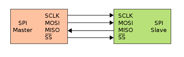
SPI uses a clock signal (CLK) and two data lanes (input & output). The data wires is called MOSI (Master Out – Slave In) and MISO (Master In – Slave Out). The clock is telling the device when to send data (and determines the speed of how often this is done, i.e. the frequency). There is also a chip select which is used for the master to tell which slave device should listen and respond on the data channels (not all devices need this tough). For now we can leave the clock signal aside, just knowing it is needed. Also, the MCP3008 do require a chip select so just leave it that it is needed and let’s not dig into why and how it works. If you need a more thorough explanation and more details on how SPI works I recommend to Google it.

Why is it important to understand the basics of SPI when all you want to do is write some code and read some values? Each type of device has it’s own particular behavior or “communication protocol”, for example which bytes that trigger a read command, and because of this it is helpful to understand the differences and get the basic knowledge needed to apply the same principles on other device types.

The data part of SPI works so that the master will send out a byte (or multiple bytes) and will expect one byte back (for each byte sent). If the master sends out three bytes this will tell the slave to perform a specific action, and then the master will listen for three bytes of data sent back from the slave. This behavior can be observed in my Troubleshooting SPI on Raspberry Pi using NodeJS guide.

Knowing this we can head on and look to the specific behavior for the MCP 3008.

The specifics for MCP3008

When using a MCP3008 as a ADC you need to know four things. First of all the device has a maximum operating frequency of ~1Mhz, and depending on the framework you are using you might have to change the SPI frequency to match the device (a lower frequency will work but each reading will take longer time). Secondly you need to know that the device has 8 analog input channels. Then you need to know MCP3008 has a 10-bit resolution, which means a single byte (8 bits) is not enough to store the maximum value (1023). Finally you need to know MCP3008 will expect three bytes for each command (transfer).

When you send a command it should contain these three bytes:

[TRIGGER] [MODE] [JUNK]

Trigger is to tell the device that you (the master) expect to receive data. The second byte, mode, tells what data you want (MCP3008 supports two different modes and eight channels). The last byte is just junk (or a placeholder for the response data). The trigger should always be a 0x01 (decimal ‘1’) and the same goes for the junk byte. The mode byte should tell which channel to read (which I leave out for now).

The response of each transfer will contain the following:

[JUNK] [MSB] [LSB]

First we have a junk byte, this is simply ignored. Then we have the Most Signifiant Byte (the “leftovers” when the first 8 bits is filled) and then we have the Least Significant Byte (the “least valuable” 8 bits of the totalt 10 bit value).

Sending the following three bytes would tell the ADC to begin reading data on channel 0 in normal mode.

0x01 0x80 0x01

And as a response we could have got these three bytes:

0x00 0x03 0xFF

In this example we got the highest possible value (1023 @ 10 bit). If we look at the bits of the MSB and the LSB they would look like this:

JNK = 0x00 = 00000000 (0)
MSB = 0x03 = 00000011 (3)
LSB = 0xFF = 11111111 (255)

The junk-byte and the first 6 bits of MSB is always ignored, and we are left with 10 bits (2+8).

00000000 00000011 11111111

With some bit shifting we can combine these two separate bytes into one 10-bit decimal value (actually it is 16 bits, or two bytes, but with a maximum value of 1023).

VALUE = (MSB << 8) + LSB = 1023

Wiring the MCP3008 to your Raspberry Pi

RaspberryPi_B+_GPIO_SPI_MCP3008_breadboard_mikael-leven
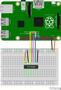
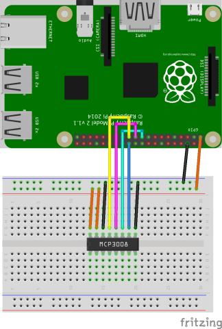
Before we can begin reading any data from your ADC you first have to wire the MCP3008 to the SPI pins on your Raspberry Pi (this example uses pin numbering for version 2 and B+).

Wire your Raspberry Pi to your MCP3008 accordingly to the following pin numbering (with the Raspi pins to the left and your ADC to the right):

  • Pin 19 (MOSI / #10) -> pin 11 (Din)
  • Pin 21 (MISO / #9) -> pin 12 (Dout)
  • Pin 23 (SCKL / #11) -> pin 13 (CLK)
  • Pin 24 (CD0 / #8) -> pin 10 (CS)
  • Pin 6 (GND) -> pin 14 (AGND) & 9 (DGND)

Now you should have a fully working SPI connection between your Raspi and ADC.

The code

Let’s write some code to read the values from MCP3008. At this stage you should ge seemingly random values (as you yet has no inputs connected generating any actual readings). Run the code below and you should expect and output similar to this:

ch0 = 112

Create a new NodeJS script with the following code (relies on the rpio npm library):

var rpio = require('rpio');

rpio.spiBegin();

// Prepare TX buffer [trigger byte = 0x01] [channel 0 = 0x80 (128)] [dummy data = 0x01]
var sendBuffer = new Buffer([0x01, (8 + 0 << 4), 0x01]); 

// Send TX buffer to SPI MOSI and recieve RX buffer from MISO
var recieveBuffer = rpio.spiTransfer(sendBuffer, sendBuffer.length); 

// Extract value from output buffer. Ignore first byte (junk). 
var junk = recieveBuffer[0],
    MSB = recieveBuffer[1],
    LSB = recieveBuffer[2];

// Ignore first six bits of MSB, bit shift MSB 8 positions and 
// lastly combine LSB with MSB to get a full 10 bit value
var value = ((MSB & 3) << 8) + LSB; 

console.log('ch' + ((sendBuffer[1] >> 4) - 8), '=', value);

(you can download the source code from gist.github.com) 

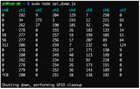
The screenshot below illustrates how the readings on all eight channels would look if they where polled repeatedly, with no input connected to the ADC, using my MCP3008 SPI Dump utility. What we see is the variation of random numbers that occur when no actual input is available.

MCP3008_ADC_SPI-dump_no-analog-input_mikael-leven

Some actual tests

Now wire channel 0 (pin 1 on your ADC) to GND and run your script once again.

MCP3008_ADC_SPI_channel-0_GND_mikael-leven

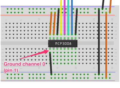
Hopefully you should now get a consistent reading close to zero (but probably not absolutely zero).

ch0 = 2

And in SPI Dump the channel 0 connected GND result would have looked like this (still random numbers for all channels but channel 0 where we have an actual input to read):

MCP3008_ADC_SPI-dump_gnd-analog-input_mikael-leven

Now connect channel 0 (pin 1) to +3.3V and run the script yet again.

MCP3008_ADC_SPI_channel-0_3V3_mikael-leven

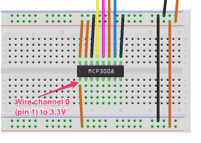
This time you should get 1023 (which is the maximum value and equivalent to the 3.3V reference voltage).

ch0 = 1023

And in SPI Dump the channel 0 connected to 3.3V would have resulted in a reading like this:

MCP3008_ADC_SPI-dump_3v3-analog-input_mikael-leven

That’s it, now you should be up-and-running with your MCP3008 ADC reading analog values and sending them as digital numbers through SPI to your Raspberry Pi. Happy coding!

Links

spi_exmple.js – Example script reading from channel 0 on MCP3008 using NodeJS
NodeJS SPI Dump for MCP3008 – Simple SPI dump utility for MCP3008 written in NodeJS
rpio npm package – Raspberry Pi GPIO library for NodeJS with support for SPI and I2C
Raspi SPI documentation – Details about the SPI driver on Raspberry Pi


Troubleshooting SPI on Raspberry Pi (in NodeJS)

When starting to use the SPI (Serial Peripheral Interface Bus) on the Raspberry PI, especially using NodeJS, it can be quite frustrating when you do not get any results (or get seemingly random data) without any obvious explanation or helpful error messages. Then this “SPI loopback” trick might come in handy.

Since SPI seems to be more straightforwards using Python in comparison to NodeJS I will focus the example code on NodeJS. The exact same approach should however be equally valid for Python.

Follow these steps to troubleshoot/debug your SPI connection on your Raspi:

1. First of all, make sure SPI is actually enabled

The SPI master driver is disabled by default on Raspian. To enable it, remove the blacklisting for spi-bcm2708 in /etc/modprobe.d/raspi-blacklist.conf, or use $ raspi-config.

If raspi-blacklist.conf looks something like this:

blacklist spi-bcm2708

Change it to (to prevent SPI from being blacklisted):

#blacklist spi-bcm2708

Reboot or load the driver manually with:

$ sudo modprobe spi-bcm2708

When you have followed these steps, or you simply want to check if SPI is enabled, run the following command:

$ ls /dev

The output should contain something like “spidev0.0” if SPI is indeed enabled.

raspberry-pi_check-spi-enabled_mikael-leven


2. Connect SPI in loopback / “debug mode”

SPI is using two data wires, MOSI and MISO. It might not be apparent what these abbreviations actually stand for. MOSI stands for Master Out Slave In (i.e. it is the input on whatever device you are trying to connect to your RasPi) and MISO stands for Master In Slave Out (i.e. the output of the device connected to your Pi, or we could call this “the Raspi Input”). Ok, so now we understand the meaning, but how will this help us debugging? If the MOSI is intended to receive data from your RasPi and the MISO is intended to send data back to your RasPi, we could simply jumper these two pins to get a “loopback” connection. Whatever data that is sent out from the Pi should get received back.

raspberry-pi_gpio_spi_loopback_nodejs_mikael-leven


3. The code – test SPI using NodeJS

This example uses the rpio GPIO library for NodeJS. Copy and paste the following code into a new file (or download the gist).

var rpio = require('rpio');

var rxBuffer = rpio.spiTransfer(new Buffer('HELLOSPI'), 8);

for (var i = 0; i <= 7; i++) { 
 process.stdout.write(String.fromCharCode(rxBuffer[i]) + (i == 7 ? '\n' : ' '));
};

Run your script as sudo:

$ sudo node your-script.js

The result should look like this:

$ sudo node your-script.js
H E L L O S P I
$ _

If you receive an error message make sure you execute node as sudo. Should you get an empty response make sure your loopback jumper wire is properly connected.

When you receive the text “H E L L O S P I” you know SPI is properly configured on your Raspberry Pi. The next step is to connect an SPI enabled device in the other end (instead of the loopback) begin writing your actual program. Good luck!

Raspberry Pi GPIO Card

RPi_B+_GPIO_Card_Mikael-LevenWhenever working with the GPIO ports of your Raspberry Pi you face challenge to remember which pin corresponds to what. E.g. which pins do I use when connecting a SPI device or where do I find the GPIO #17 pin?

To assist this I have put together a printable GPIO Card you easily can fit directly on your GPIO header. Although initially made for the 40 pin GPIO header of the A+, B+ and the version 2 model B boards, you could easily fit it on a version 1 model B rev 2 board as well (simply ignore the last 14 pins).

Check out the printable Raspberry Pi GPIO Card

Troubleshooting “digispark” (ATtiny85) on Mac OS X

attiny85-breakout-boardIf you encounter problems programming your “digispark” this info might be helpful. First of all I will assume you have followed the getting started guide on the Digistump wiki (Connecting and Programming Your Digispark). Should you after completing these steps experience issues with programming your “digispark”, check out these basic troubleshooting tips (try different cables, USB hubs etc).

In addition to the tips mentioned above you might also experience an error similar to this:

java.io.IOException: Cannot run program "/Users/{USERNAME}/Library/Arduino15/packages/digistump/tools/micronucleus/2.0a4/launcher": error=13, Permission denied

If you get this error this might be caused due to security restrictions and you need to make the micronucleus tools executable on your machine. Run the following commands (your actual path may vary, i.e. due to a different version of micronucleus):

$ cd ~/Library/Arduino15/packages/digistump/tools/micronucleus/2.0a4/
$ chmod a+wx launcher
$ chmod a+wx micronucleus

Complete error message:

Read More

Please Stop These Annoying Cookie Popups

cookies1Ok, I get the basic idea with these cookie messages. It is to protect our privacy. Sure. But why do they need to be so annoying? And why does they all behave in different ways?

A far better solution would be to manage this natively in the browser, rather than having each individual website to manage this. Moving this responsibility would be good in two ways. First of all, not every website owner would have to reinvent the wheel and develop their own solution. Even more importantly we should get a consistent user experience. There is quite a few bad examples out there, and sure there is some pretty decent implementations as well, however it is still a very inconsistent user experience.

cookies3

cookies2

My proposal for all the web browser developers out there would be to add native support for cookie information. Since most websites anyway simply informs about the use of cookies and urge you to leave the website if you do not comply, this would be rather easy to achieve. However while addressing this issue it would be a good idea to take this one step further and let the user decide wether or not to generally always accept cookies (and most of us probably do anyway already). We could also get the choice to easily explicitly disable cookies for a specific website.

I have no detailed proposal, but basically each website should only need to present a short message about how they utilize cookies and supply a url to a website with more detailed information. Given that this information is present in the source code (in a meta-tag?) the web browser could decide how to present this to the user in a uniform manner. And my suggestion here is a solution similar to how secure websites would be displayed in modern browsers. Consider these sketches:

Browser_CookiePrivacy_Ok_MikaelLeven

Browser_CookiePrivacy_Choice_MikaelLeven

Browser_CookiePrivacy_Disabled_MikaelLeven

Two Great News From Heroku

Heroku has announced two interesting features:

Heroku Private Spaces Beta opens up for additional security and control in your cloud solution. Read more about Heroku Private Spaces: Private PaaS, delivered as-a-Service.

Heroku Flow enables Continuous Delivery via GitHub, making CD visual, easy to manage, and accessible to all team members. Read more about Heroku Flow – a new and flexible way to structure, support, and visualize your CD workflow.

Your First Raspberry Pi: A Buyer’s Guide

Pi_2_Model_BI found this great post about the choices you need to make when buying your first Raspberry Pi. Although being a great guide when deciding about which model to choose and what complementary hardware you need, it is a bit outdated. I would recommend you read the guide, however with following additions:

Model A vs A+

This is the differences with A+ compared to the initial Model A:

  • More GPIO. The GPIO header has grown to 40 pins, while retaining the same pinout for the first 26 pins as the Model A and B.
  • Micro SD. The old friction-fit SD card socket has been replaced with a much nicer push-push micro SD version.
  • Lower power consumption. By replacing linear regulators with switching ones we’ve reduced power consumption by between 0.5W and 1W.
  • Better audio. The audio circuit incorporates a dedicated low-noise power supply.
  • Smaller, neater form factor. We’ve aligned the USB connector with the board edge, moved composite video onto the 3.5mm jack, and added four squarely-placed mounting holes. Model A+ is approximately 2cm shorter than the Model A.

Recommended for embedded projects and projects which require very low power, and which do not require Ethernet or multiple USB ports.

Mode B vs B+

Model B+ should not be mixed up with the Model B Rev 2 (which is simply a slightly updated Model B rev 1with minor differences). However, the differences between Model B and B+ is on the other significant.

  • More GPIO. The GPIO header has grown to 40 pins, while retaining the same pinout for the first 26 pins as the Model A and B.
  • More USB. We now have 4 USB 2.0 ports, compared to 2 on the Model B, and better hotplug and overcurrent behaviour.
  • Micro SD. The old friction-fit SD card socket has been replaced with a much nicer push-push micro SD version.
  • Lower power consumption. By replacing linear regulators with switching ones we’ve reduced power consumption by between 0.5W and 1W.
  • Better audio. The audio circuit incorporates a dedicated low-noise power supply.
  • Neater form factor. We’ve aligned the USB connectors with the board edge, moved composite video onto the 3.5mm jack, and added four squarely-placed mounting holes.

The Model B+ is perfectly suitable for use in schools: it offers more flexibility for learners than the leaner Model A or A+, which are more useful for embedded projects and projects which require very low power, and has more USB ports than the Model B.

The New Raspberry Pi 2

The Raspberry Pi 2 is the next generation of Model B/B+, and it is not even mentioned in the original post. It basically is a beefed up Model B+ with better CPU and more RAM, making it even more suitable for HTPC, NAS and similar usages.

Because it has an (quad-core) ARMv7 processor, it can run the full range of ARM GNU/Linux distributions, including Snappy Ubuntu Core, as well as Microsoft Windows 10. And due to being more powerful the “Pi 2” will be slightly more power-hungry compared to the Model B+ (up to about 0.5-1w more), and especially compared to the Model A+.

Original post

http://computers.tutsplus.com/tutorials/your-first-raspberry-pi-a-buyers-guide–mac-54134